IFSEC Insider is operated by a business or businesses owned by Informa PLC and all copyright resides with them. Informa PLC's registered office is 5 Howick Place, London SW1P 1WG. Registered in England and Wales. Number 8860726.
By Peter Massingberd-Mundy of Xtralis, Hemel Hempstead, UK and Nitin Vayeda, Xtralis, Melbourne, Australia
Abstract
The assessment of drift compensation algorithms to ensure there are no negative effects on the response of a smoke detector to a slowly developing fire is a complex and confusing topic. The details of how drift compensation is actually achieved is generally regarded as proprietary information but when poorly implemented there is a risk that the compensation algorithms may alter the detectors actual sensitivity to smoke – particular their response to a slowly developing fire or to fire that occurs in an environment where there is a high “background”. The requirements specified in the appropriate parts of the EN 54 series of products standards related to these issues have been in place for many years.
However, the assessment is restricted to checking the performance to a slow growth fire only. Furthermore, the assessment is typically undertaken by a detailed but limited review of the circuits and software that effect the long term compensation / response of the detector because the challenges associated with creating and measuring a very slow ramp of smoke or a low but consistent level of smoke are deemed to be too expensive to overcome. This paper reviews these challenges and describes a simple, practical and low cost rig for achieving consistent and controllable low concentrations of smoke which has proved extremely effective in assessing the behaviour of ASD systems.
Introduction
Use of drift compensation is widespread in fire detectors. It may be presented as an adjustment or a correction to the analogue signal coming from the sensor (smoke, temperature etc.) before it is presented to the alarm algorithms or it may be manifested as an adjustment to the thresholds or algorithms themselves.
Whatever the technique, the fundamental outcome is an adjustment to the way a detector responds to the signal(s) being measured by its sensor(s).
This poses some challenges for anybody assessing the performance of a smoke detector which incorporates drift compensation – or more fundamentally, those writing the standards that define how to assess the performance of such a detector. The backbone to any product assessment is the ability to successfully measure sensitivity of a detector despite any adjustment for drift and this is achieved by making sure that every test starts from a controlled position.
For example, for a smoke detector to EN 54-7, the smoke tunnel must be sufficiently purged and stabilized for a period of “at least” 15 minutes before initialising the smoke ramp which is used to determine when (i.e. at what smoke obscuration) the detector signals an alarm. Thus it is expected that the effects of any drift compensation algorithms will be negated (or negligible) during the measurement of sensitivity.
The current standards only consider one possible consequence of drift compensation by requiring that it does “not lead to a significant reduction in the detector’s sensitivity to slowly developing fires” (as expressed in EN 54-7, EN 54-12, EN 54-20, prEN 54-29, prEN 54-31).
These particular standards (with the exception of EN 54-12) then state that… “Because/Since it is not practical to make tests with very slow increases in smoke density, an assessment of the detector’s response to slow increases in smoke density shall be made by analysis of the circuit/software, and/or physical tests and simulations.”
This statement is no longer true because it is now practical to make tests with very slow increases in smoke density. Moreover it is also possible to generate consistent low levels of smoke in order to assess the effects of prolonged high background levels on the sensitivity of a drift compensated detector. When such tests are applied to approved detectors – the results can be quite alarming!
This paper reviews the long established requirements for the response to slowly developing fires and describes a simple, practical and low cost rig which achieves consistent and controllable low concentrations of smoke which can be used to make practical tests to assess detectors to these requirements and more.
Summary of the current requirements
Each of the EN 54 standards referred to in the introduction above states the requirements for the response to “slowly developing” fires as follows:
a) for any rate of increase in smoke density R, which is greater than A/4 per hour (where A is the detector’s initial uncompensated response threshold value), the time for the detector to give an alarm does not exceed 1,6 × A/R by more than 100 s; and
b) the range of compensation is limited such that, throughout this range, the compensation does not cause the response threshold value of the detector to exceed its initial value by a factor greater than 1,6.
They all then provide further background and information on these requirements in an annex. Despite this many people remain confused.
The requirements (as discussion in the annexes) only consider the use of compensation to avoid false alarms due to “upward drift in the sensor output”. In such cases the detector’s compensation will reduce its sensitivity to avoid a false alarm and, if this compensation is applied too quickly, may result in a very poor response to a slowly developing fire. The standards do not consider cases where contamination may lead to a reduction in the detector’s sensitivity to smoke and the possibility that the compensation should increase its sensitivity to avoid missing a fire event.
Furthermore they make no specific requirements in relation to reducing the compensation – thus detectors covering environments with a variable, noisy or high background signal could compensate to match the periods of high background (typically during occupation of the premises) such that during periods of low background (e.g. overnight) they are unacceptably insensitive.
By “slowly developing fire” the standards consider that a fire, which develops linearly and would be detected after 4 hours by an uncompensated detector, should be detected within 6.4 hours by a compensated detector! (from 4×1.6 as described in the annexes). It is quite a generous limitation and it should be expected that most compensated detectors will not increase the detection time to this extent.
However, the standard actually allows for much faster rates of compensation as long as the detection time is not increased by a factor of more than 1.6 as a result of the compensation. Thus a fire that might be detected within 6 minutes could be delayed to nearly 10 minutes by a detector with fast compensation algorithms in place.
In practice this is unlikely to be an issue as compensation is unlikely to be applied so quickly. What is more concerning is that for very slow rates of compensation (i.e. less than A/4 per hour – see a) above) there is no limit to the amount of compensation that can be applied so “there is no requirement for the detector to respond to these lower rates of change“.
Thus a fire that may take five hours to develop can remain undetected indefinitely.
Discussion
It is not the purpose of this paper to present an alternative way to express the requirements for limiting the effects of drift compensation but it is clear from the above section that the current requirements are not as robust as they might appear to be. For example, is it possible for a detector to apply compensation very slowly, indefinitely and never reduce that compensation. Thus a detector exposed to a high background for a single day (e.g. as the result of a local forest fire) could thereafter be very insensitive to a fire threat during periods where the background signal returns to normal low levels.
Instead, the focus of this paper is to consider the recommendation that the assessment is performed by “analysis of the circuit/software and/or physical tests and simulations” because it is presumed that it is “not practical to make tests with very slow increases in smoke density”.
The pros and cons of an analytical assessment vs testing
The following table presents a simple comparison of the two fundamental approaches to assessment.
Consideration
Assessment method
Analysis/simulations
Testing
Breadth of the assessment
Many scenarios can be considered. Analysis may allow assessment to focus on the most likely failure points. Simulations can be run faster than real time.
Focuses on few specific scenarios. However, within a 24 hour period it should be possible to include several smoke ramps/profiles (including, for example; the limiting rate of A/4 /hour, several faster rates and one or two slower rates) and also include a test to assess the effect of a high background.
Depth of the assessment
The quality of the source code and documentation determines how accurate the understanding of the compensation algorithm is. A full understanding is needed to be sure that the analysis/simulations are representative of the complete system from the sensor to the alarm output.
Tests the response to a slow developing fire (or high background) from the smoke sensor to alarm output without a detailed understanding of the drift compensation algorithms.
Clearly there is value and limitations for both assessment methods so undertaking an assessment using either one alone is not desirable and excluding one on the presumption that it is not practical is inappropriate.
Practical realisation of a controlled smoke density
Creating, controlling and measuring “smoke” reliably and repeatedly has its challenges – particularly when the period of the test is prolonged. This is because there is a tendency for the characteristics of a smoke to change over time and for any measurement technique to drift.
Fundamentally these two challenges can be countered by using smoke which is pre-aged and by using a stable reference measurement which is periodically cross-checked to a second, “clean”, reference detector /sensor.
A large scale Smoke Test Facility (STF) was developed with these remedies in place and provided a practical solution for testing the response of a smoke detector to slow increase in smoke density and also measuring its sensitivity after a prolonged period of exposure to a high or varying background. The STF was developed by Xtralis for the purposes of competitive benchmarking and results from it have been independently observed and endorsed by a well-respected international organisation. and have been published1
The experience gained in the use of the large scale STF has led to the development of a smaller scale test rig. The MiniSTF offers a practical realisation of the control and slow increase in smoke density over a prolonged period so is ideally suited to the assessment of the compensation algorithms used in detectors to ensure that their response to slowly developing fires is not unduly impaired.
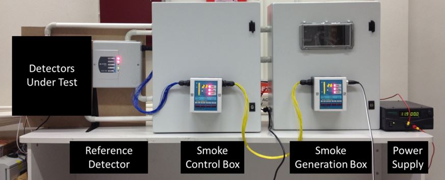
The MiniSTF rig complete
There are two key aspects to the MiniSTF. Firstly it has two separate smoke compartments – in the first compartment, smoke is generated and controlled to a predetermined level to provide a reservoir of aged smoke which can be drawn into the second compartment on demand. The second key aspect is that the smoke density within each compartment is closely controlled using two simple feedback loops incorporating very stable VESDA aspirating detectors. These feedback detectors are independent of a third reference detector which does not sample continually (because it may become contaminated) but rather it is used to periodically confirm that the required smoke density is being achieved/maintained by the detectors in the two feedback loops. In the example presented herein the reference detector is a third VESDA aspirating detector but it does not have to be.
Inside the “smoke generation box” a wooden frame supports a PVC wire (as specified in BS6266:2011) which is overheated. Power to the wire is controlled using feedback form a VESDA VLC detector installed within the box. With this simple feedback control the smoke density in the smoke box is controlled close to the fire threshold of the VLC to provide the reservoir of “aged” smoke. Smoke sources other than a PVC wire could be used.
Inside the “smoke control box”, a second VESDA VLC detector is used to provide simple feedback control to hold the smoke density in the smoke control box close to the fire threshold set by this second VLC detector.
Why use a VESDA detector?
While the concept of the MiniSTF is relatively simply, it relies fundamentally on the stability of the two feedback detectors. Unlike many ASD detectors, a VESDA detector does not use drift compensation to compensate for any contamination. Instead clean air is created within the detector (using the aspirator and a two stage filter) which is used to create a clean air barrier for the critical optical components within the detector. Thus, even though the system is sampling over several hours for many days it has been proven to maintain a consistent smoke level.
While a VESDA detector may also be suitable for the reference detector this does not have to be the case as the reference detector only needs to operate periodically – i.e. often enough to provide confirmation that the two feedback detectors are stable and performing as expected. Clearly an aspirating detector is most suitable as it is can be conveniently isolated from the mixing box when not sampling. If necessary two reference detectors could be used – with different sampling periods.
More sophisticated control of the set level.
While the simple feedback control described above is easy to implement and can be used to maintain a constant level of smoke around a fixed Fire threshold setting of the detectors, it is possible to implement a ramp by either dynamically altering the fire threshold or controlling the flow in to the smoke control box or both. With the VESDA detectors this adjustment can be automated using an open protocol High Level Interface (HLI) though which a PC can set the fire thresholds to achieve any smoke profile over a prolonged period of time.
Sample of results from the MiniSTF:
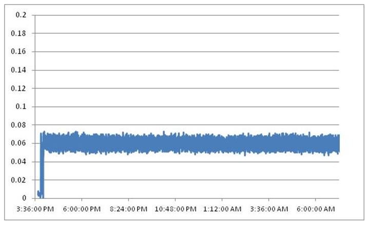
Figures 2 shows the typical controlled smoke signal from the VESDA VLC in the smoke control box maintained over a 16 hour period. The smoke level is held at the fire threshold (0.06%/m) within ±0.01%/m. It represents a 15% variation at this very low level of smoke and demonstrates the ability of the miniSTF to maintain a smoke level within acceptable range. The MiniSTF can be set for any target smoke density in order to assess the effects of drift compensation.
0.06%/m controlled smoke density over 16 hours
With a little further development the MiniSTF could conveniently run several smoke profiles consecutively to conveniently assess the response of a detector to various slow developing fires after a prolonged period of high background. Moreover, if could be used to run fast ramps between each test to assess the response of the detector. The MiniSTF thus achieves a practical, automated method for assessing the effects of drift compensation.
Conclusion
This paper highlights the following points:
Current standards only assess the effects of drift compensation on the ability of a detector to respond to a slowly developing fire. They do not assess the effects of drift compensation in environments with a prolonged low or fluctuating background level.
Current standards state that it “is not practical to make tests with very slow increases in smoke density” and they recommend the use of analysis and simulation to assess the response of a detector to a slow fire.
The MiniSTF rig described, incorporating two smoke chambers and simple feedback to control the smoke density in each chamber, has been found to provide a practical method for achieving a controlled density of smoke over prolonged periods and can also be configured to provide slow smoke ramp– thus refuting the statement highlighted in point 2.
The MiniSTF rig could be automated to run consecutive smoke profiles with a response test in-between thus achieving a very cost effective and comprehensive way to assess the effects of drift compensation.
References
[1] Xtralis Aspirated Smoke Detector Exposure Testing: Full Report of Tests, Joshua Dinaburg Daniel T Gottuk Hughes Associates, Inc. December 18, 2012, revision February 7, 2013.
Listen to the IFSEC Insider podcast!
Each month, the IFSEC Insider (formerly IFSEC Global) Security in Focus podcast brings you conversations with leading figures in the physical security industry. Covering everything from risk management principles and building a security culture, to the key trends ahead in tech and initiatives on diversity and inclusivity, the podcast keeps security professionals up to date with the latest hot topics in the sector.
Available online, and on Spotify, Apple Podcasts and Google Podcasts, tune in for an easy way to remain up to date on the issues affecting your role.
A Practical Method for Testing Smoke Detectors With Drift Compensation on Slowly Developing Fires and High Background LevelsBy Peter Massingberd-Mundy of Xtralis, Hemel Hempstead, UK and Nitin Vayeda, Xtralis, Melbourne, Australia.
-- --
IFSEC Insider | Security and Fire News and Resources
Related Topics
Schools invest in vape detection systems as vaping incidences among children rise
Aico expands range of multi-sensor fire alarms with Ei660i and Ei660iRF
AI-based warning system S.A.F.E designed to spot early signs of smoke and fire