IFSEC Insider is operated by a business or businesses owned by Informa PLC and all copyright resides with them. Informa PLC's registered office is 5 Howick Place, London SW1P 1WG. Registered in England and Wales. Number 8860726.
Fault finding is a key component of many fire engineers and installers day-to day lives. Whether it’s during the installation and commissioning stage, regular maintenance inspections or emergency callouts. Here, Apollo Fire Detectors explores the causes of the most common faults that you could expect to see on site, and explains how its Apollo Test Set can assist you to find and resolve faults.
What are the most common faults that you can expect to find on site?
During commissioning it is common to find a plethora of faults which can take anywhere between an hour and a day to fix.
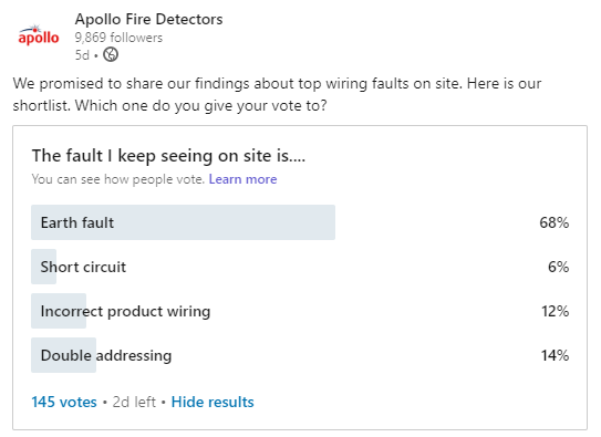
Our survey of common faults shows:
Other common faults include:
drawings do not reflect actual installation
heads not connecting to bases properly
incorrectly set address
Fault finding is carried out by:
checking loose wiring connections
checking for faulty devices (which may have been vandalised)
checking battery levels
taking the loop apart to narrow down the fault location
It is always helpful to gather as much information as possible before taking things apart or resetting panels, and to be methodical as you check the system to identify faults.
How the Apollo Test Set can help
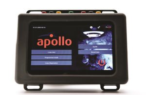
The Apollo Test Set was designed to assist engineers in managing Apollo loops and aid in fault finding. It is a portable loop tester featuring a touch screen display capable of providing several functions in interrogating and controlling all devices connected to the unit, either individual devices or complete circuits of analogue addressable devices in the Apollo ranges (Soteria, Discovery and XP95).
The Apollo Test Set key features include:
Loop connection ports for individual addressing or fault finding
Loop integrity and diagnostics testing during commissioning and maintenance
Review of device information and control functionality modes
The two main test set functions that help you to identify faults are the Loop Diagnostics Mode and the Loop View Menu. Below, we explain what they are and what faults they help to address.
Loop Diagnostics Mode
Loop Diagnostics Mode is best for handling wiring faults such as earth fault, short and open circuits.
Loop Diagnostics Mode is used for:
Wire connection test
Loop voltage and current measurement
Short circuit fault test
Loop cable impedance measurement
Earth fault test
Automatic detection of earth fault location
These tests and measurements are divided into four groups:
Short circuit fault/earth fault detection – This is the core test of loop diagnostics. It shows the results of the wire connection test, short circuit fault test, earth fault test and loop cable impedance measurement. The first thing tested is the loop integrity.
If there is a broken wire or it is not plugged into a socket, a warning message ‘Wire connection issue’ appears. In addition, it will tell you which wire is carrying the fault.
If an earth fault or short circuit is detected test Set will show warning messages.
Loop supply – from OUT – voltage and current measurement
Loop supply – from IN – voltage and current measurement
Earth fault location search
So, how does the Loop View function help us handle an earth fault?
The Loop View function will tell you if there is a fault and if it’s earth to positive or negative (e.g. yes there is an earth fault between +ve and screen or -ve and screen) but it will not provide an exact location. Then the engineer will need to work their magic to break the loop down and see which section the earth fault occurs in.
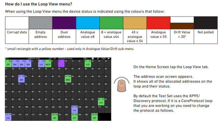
Loop View menu
Loop View Menu is best for handling
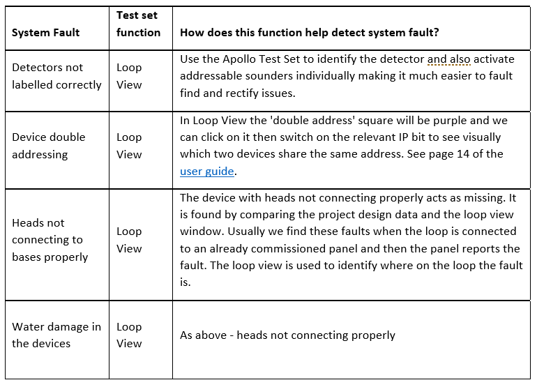
Incorrect detector labelling
Device double addressing
Faults due to water damage in the devices
Faults due to loss of connection between the head and the base
Loop View Menu is used to:
Select a polling range
View the details of a single address
Change the output bit status
Self-test
Fast Test
Isolator control – The Isolator Control button is used to switch the device isolator on or off
Configuration status – Tap the Configuration Status button to show the configuration status of any Soteria device on the loop
Mode and polling LED – This menu enables you to see the mode and LED status of the devices on the loop.
Analogue Value/Drift – This menu enables you to view the analogue and drift values of the devices on the loop.
Here are some common system faults that could be addressed with the Loop View function in the Apollo Test Set.
Enjoy the latest fire and security news, updates and expert opinions sent straight to your inbox with IFSEC Insider's essential weekly newsletters. Subscribe today to make sure you're never left behind by the fast-evolving industry landscape.
TECH TALKS: Fire loop fault finding with the Apollo Test SetApollo Fire Detectors explores the causes of the most common faults that you could expect to see on site, and explains how its Apollo Test Set can assist you to find and resolve faults.
IFSEC Insider
IFSEC Insider | Security and Fire News and Resources
Related Topics
Tech Talks: The importance of insulation and continuity testing of fire cables
FIREX Tech Talks: Apollo Fire Detectors – Soteria Dimension
 The Apollo Test Set was designed to assist engineers in managing Apollo loops and aid in fault finding. It is a portable loop tester featuring a touch screen display capable of providing several functions in interrogating and controlling all devices connected to the unit, either individual devices or complete circuits of analogue addressable devices in the Apollo ranges (Soteria, Discovery and XP95).
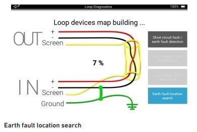 These tests and measurements are divided into four groups:
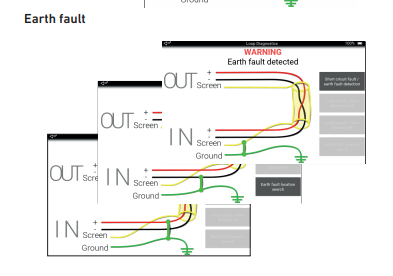 Loop View menu